- Importance of Electrical Wiring for Air Conditioning Systems,
- How to get the Electrical Wiring for Air Conditioning systems?,
- Types of Electrical Wiring Diagrams For Air Conditioning Systems,
- How to read Electrical Wiring Diagrams?
Today, I will explain Electrical Wiring for different Air-Conditioning Systems Types and Equipment.
Third: Electrical Wiring Diagrams for Air-Conditioning Systems - Continued
|
The Electrical wiring diagrams for Typical Air conditioning equipment
The main types and equipments in common Air conditioning systems were:
|
1- Window Air Conditioning Units
|
1.2 The power flow in Branch circuit of a Typical Window air conditioning unit
|
1.3 Electrical wiring connections inside The Window air conditioning units
Here we are interested on how the main power cord is connected inside the unit and this can be explained as follow (see Fig.4):
A- Inside the unit the main power cord is split to:
B- Hot wire goes to the selector switch on a window unit to feed power to the vital parts, compressor and fan motor as follows:
C- Neutral wire will be connected to fan motor and compressor without goes through any switch. These connections are made on the wire connector in the back of the selector switch so, all neutral wires are common to each other because they are connected to the same point.
some examples for the complete electrical wiring diagrams for Window Air Conditioning Unit are inFig.5.
|
1.4 The power flow inside a Typical Window air conditioning unit in the cooling mode
|
2- Split Air Cooling Units
|
2.1 Split air Cooling Units Construction
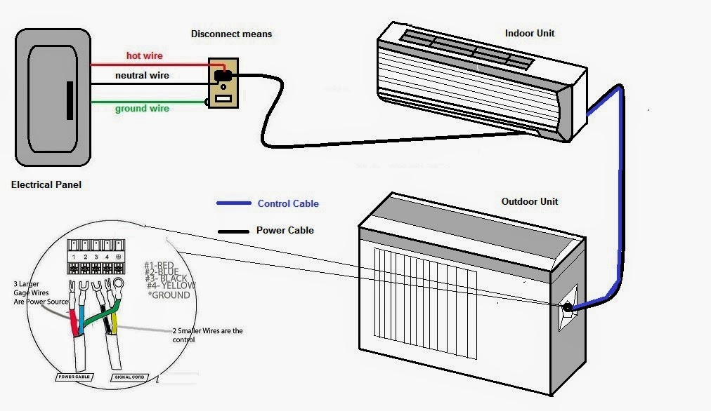
The split systems are individual systems in which the two heat exchangers are separated (one outside, one inside) (see Fig.8). There are two main parts of the split air conditioner which are:
1- Outdoor unit:
This unit is installed outside the room or office space which is to be cooled and houses important components of the air conditioner like:
2- Indoor unit:
The most common type of the indoor unit is the wall mounted type though other types like ceiling mounted and floor mounted are also used. The indoor unit produces the cooling effect inside the room or the office and houses the following components:
|
2.2 The power flow in Branch circuit of a Typical split air conditioning unit
The split air conditioning units are fed from either:
Or
Note:
if power source connections made in indoor unit, an indoor disconnecting means is used and if power source connections made in outdoor unit, an outdoor disconnecting means (see Fig.14) with suitable identity of protection (IP) is used (review the manufacturer’s recommendations and wiring diagrams).
Note:
There is a signal cable also connecting the control in the indoor unit with the control in the outdoor unit.
|
2.3 Electrical wiring connections inside The Split air conditioning units
|
3- Multi-Split Air Conditioners
|
3.1 The power wiring for multi-split air conditioners
in Fig.18, you can find examples for the complete wiring diagrams for Multi-split air conditioners.
|
4- Mini- Heat Pumps
|
4.1 The power wiring of Mini- Heat Pumps
The power wiring of Mini- Heat Pumps will look like that of the Split air Cooling Units for far extent (seeFig.19).
However, you can find in below some examples for wiring diagrams for Mini- Heat Pumps (see Fig.20) and you can compare them with that of Split air Cooling Units especially in the power (high voltage) wiring.
|
5- Split Packaged Units
|
5.1 Split Packaged Units Construction
A split system describes an air conditioning or heat pump system that is split into two sections (see Fig.21)which are:
1- Outdoor section:
The outdoor unit is located outside usually on the ground but sometimes on the roof. It houses the following components:
2- Indoor section:
The indoor section usually located in an interior closet or garage. It houses the following components:
|
5.2 The Electrical wiring in Split Packaged units
The Electrical wiring in Split Packaged units consists of 3 main parts as follows:
1- High voltage part (power part):(see Fig.22)
The branch circuit will originate from one of the three pole Overcurrent protective device OCPD included in an electrical panel.
Then go through raceway system (conduits, ducts, …) to :
2- High voltage control and motors part:
3- Low voltage control part:
This part has (2) mode for operation which are:
A- In the A/C Mode:
The thermostat send signal in (2) directions as follows:
B- In the heat Mode:
Also, the thermostat, in this mode, sends signal in (2) directions as follows:
So, the complete wiring diagram will be as in Fig.26 below:
Note:
The thermostat usually have (5) positions which are Off – Cold – Auto – Heat – on.
You can find in below some examples for wiring diagrams for split packaged units with different starting methods in Fig.27.
|
6- Unitary Packaged Units
|
6.1 The power circuit for Unitary packaged units
The power Schematic diagram for Rooftop packaged units is shown in Fig.29.
|


There are lot's of Pre Fabricated Duct Suppliers and exporters in India, But I found your service much reliable then others, If you are looking for Pre Fabricated Duct in India this will be the right place for all your need.
ReplyDelete